Language
How to set up the 33U controller of iron ring copper ring pneumatic butt welding machine
Wuxi Xinxing Welding Equipment Factory mainly produces: spot welding machines, butt welding machines, flash butt welding machines, medium frequency spot welding machines, energy storage spot welding machines, nut spot welding machines, polymer diffusion welding machines and other resistance welding equipment! QQ online consultationSitemapContact us

Xinxing. Intelligent resistance welding equipment and solution service provider 33 years of deep experience in the industry help companies solve difficult welding problems and improve welding efficiency!

 National service hotline:400-001-050213395100070
How to set up the 33U controller of iron ring copper ring pneumatic butt welding machine
Release time:2022.03.12
Summary of information:
The iron ring and copper ring pneumatic butt welding machine is also called the metal ring butt welding machine. Xinxing Welding uses a complex and intelligent 33U controller to control it. Although there are many parameters, the setting is not difficult. Just follow the instructions below. (1) Standard/first-level menu parameter setting
Iron ring copper ring pneumatic butt welding machine also known asMetal ring butt welding machine, Xinxing Welding is controlled by a complex and intelligent 33U controller. Although there are many parameters, the settings are not difficult. Just follow the instructions below.
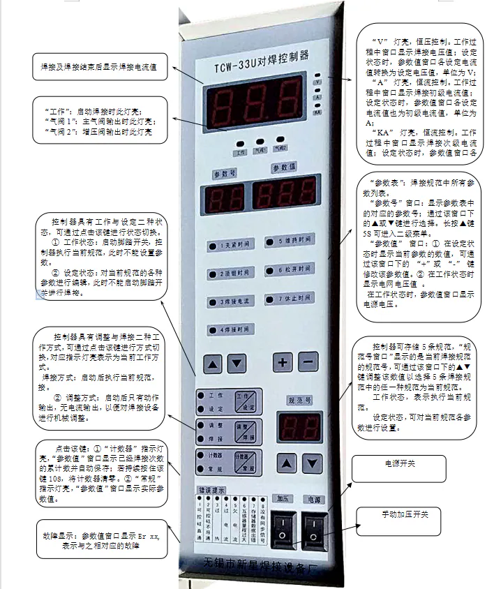
(1) Standards/First level menu parameter setting
When this controller is working, it hasThe 7 parameters (see the table below) need to be set by the user according to the actual situation. When setting the parameters, the controller should be in the setting state, preset a specification number, then press the ▲ ▼ keys to select the parameter number, and then set the parameter value through the "+" "-" keys:
|
parameters No. |
parameters Name |
Setting range |
Function description |
||
|
1 |
clamping time |
0-250 cycles |
The time interval from when the system starts, the main air valve moves to pressurize, to the upsetting air valve output |
||
|
2 |
Upsetting time |
0-250 cycles |
The time interval from the action of the upsetting gas valve to the output of welding current |
||
|
3 |
welding current |
0-999 |
Welding current value |
Constant voltage control: setting range0-450V |
|
|
Constant current control |
Beginner: Setting range0-999A |
||||
|
Secondary: Setting range0-99.9KA |
|||||
|
4 |
Welding time |
0-250 cycles |
The duration of the welding current on the workpiece |
||
|
5 |
maintenance time |
0-250 cycles |
After the current is cut off, the electrode continues to maintain pressure on the workpiece for a period of time. When the time is up, close the main air valve. |
||
|
6 |
Release time |
0-250 cycles |
The time interval from the main air valve closing to the upsetting valve closing, the release time is set toAt 0 o'clock, the main air valve and the upsetting valve are closed at the same time. |
||
|
7 |
Rest time |
0-250 cycles |
During continuous welding, the time interval between two welding processes |
||
Note:
1. When using transformer sampling, if the transformer range is less than 100A, the controller will automatically increase the control accuracy to 0.1A, that is, the current setting range is 0-99.9A.
2. When using induction coil sampling, if the range of the induction coil is less than 10.0KA, the controller will automatically increase the control accuracy to 0.01KA, that is, the current setting range is 0-9.99 KA.
(2) Secondary menu parameter setting
Keep pressing"Parameter number" under the window▲" key for about 5 seconds to enter the secondary menu (after entering the secondary menu, when only the last digit of the parameter value window is displayed, "Password bit”,Passable"+, -" keys to modify), the meaning of each parameter is as follows:
|
Parameter name |
code name |
Setting range |
Gong can say Ming |
||
|
Start mode |
P |
0 |
Pulse signal start, debounce (applicable to foot switch) |
||
|
1 |
Pulse signal start, fast response (suitable for mechanical contacts) |
||||
|
2 |
Switch signal starts |
||||
|
constant current/constant voltage Control method |
A |
0 |
Constant voltage control method |
||
|
1-999 |
Constant current control method, the meaning of parameter setting is determined by the b value: When b=0, it is the primary transformer sampling, its value is the current transformer range, the unit is (A); When b=1, it is the secondary induction coil sampling, its value is the induction coil range, the unit is (KA) |
||||
|
Beginning/subsampling |
b |
0 |
Primary sampling:A is the transformer nameplate calibration value, the unit is (A) |
||
|
1 |
Secondary sampling:A is the range value of the induction coil, the unit is (KA) |
||||
|
Current upper limit alarm |
AH |
0-100% |
When the actual value of welding current﹥set value* (1+AH) alarm, display overcurrent Er04Note1 |
||
|
Current lower limit alarm |
AL |
0-100% |
When the actual value of welding current﹤set value* (1-AL) alarm, display under current Er05Note2 |
||
|
secret code point |
4 |
Thermal protection switch mode |
AA |
0 |
Overheating protection, normally open contact of external thermal protection device |
|
1 |
Overheating protection, normally closed contact of external thermal protection device |
||||
|
Auxiliary output |
Ab |
0 |
After an error message appears, there is no auxiliary action output. |
||
|
1 |
After an error message appears, there is an auxiliary action output Note3 |
||||
|
constant current/constant heat mode |
AC |
0 |
Constant voltage mode or constant current mode (byA value selected) |
||
|
1 |
constant heat method |
||||
|
|
Ad |
|
Internal parameters are set at the factory and cannot be modified by the user. |
||
|
Filter order |
AE |
0-5 |
Under normal circumstancesAE can be set to 0. When interference occurs, the filter order can be set. When the filtering function is turned on, AF is generally set to 20-30. |
||
|
Filter range |
AF |
0-100 |
|||
|
5 |
|
d |
Alternate parameters |
||
|
Error prompt mode selection |
T |
0 |
When an error message appears, terminate the current specification immediately and activate the foot switch to continue working. |
||
|
1 |
When an error message appears, terminate the current specification immediately, you need to press the "Work/Set" button to clear the error message before you can start the foot switch to continue working. |
||||
|
2 |
Close error message |
||||
|
Standard selection |
C |
Spare |
|||
Note:1. When the "AH" setting value is "0", the current upper limit alarm function is turned off.
2. When the "AL" setting value is "0", the current lower limit alarm function is turned off.
3. This function and the auxiliary air valve share a set of outputs. Only one of this function and the auxiliary air valve can be selected.
(3) Control mode selection:This controller hasPrimary constant current, secondary constant current, constant voltage, constant heatFour control modes are available for users to choose from, and the factory setting is constant voltage control.
2. Parameter settings and instructions for various control methods
|
Control method |
Sampling device |
Parameter settings |
Description |
||
|
primary constant current |
Current transformer |
A=Transformer range |
b=0 |
AC=00 |
The current setting value and display value are the primary current values of the welding transformer, unitA, range 0-999A |
|
secondary constant current |
induction coil |
A=Induction coil range |
b=1 |
AC=00 |
The current setting value and display value are the secondary current values of the welding transformer, unitKA, range 0-99.9KA |
|
constant voltage |
Internal sampling of the controller, no need for external sampling devices |
A=000 |
b=0 |
AC=00 |
The current setting value and display value are the primary voltage values of the welding transformer, unitV, range 0-450V |
|
constant heat |
All of the above are available |
All three of the above are available |
AC=01 |
The current setting value is a thousandth of the total power of the welding transformer, and the setting range is:0-999‰, the displayed value is: A, KA or V |
|
Note:1. When the secondary constant current control method is selected, the factory's special induction coil must be used. The factory's induction coil has three specifications for users to choose, namely: 0-10KA, 0-30KA, 0-60KA. If the 0-10KA specification is selected, that is, when A is set to 10.0, the controller accuracy is automatically increased to 0.01KA, that is, the current setting range is 0-9.99 KA.
2. When selecting primary constant current, if the current required by the user is small and the selected transformer is ≤100/5, the controller will automatically increase the control accuracy to 0.1A, that is, the current setting range is 0-99.9A.
Hot product recommendations
-
300KVA copper bar soft connection diffusion welding machine
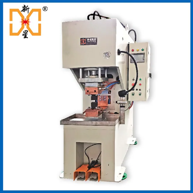
Power: 300KVA Model: DBTH-300 Overlap: Copper skin, copper strip, copper foil soft connection, stainless steel, etc., and can also weld dissimilar materials. The hydraulic high-power medium-voltage medium-frequency copper bar soft connection diffusion welding machine mainly welds the same multi-layer copper strip, copper foil and copper skin into soft and hard copper bar connectors. It can also weld stainless steel strips, titanium zirconium and tantalum strips and multi-layer dissimilar materials. Mainly used for conductive connections in new energy vehicles, electric power stations, electrical switches, smelting power supplies, welding machines and other industries.
-
150KVA copper strip soft connection diffusion welding machine
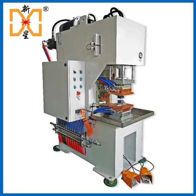
Power: 150KVA Model: DBTH-150 Overlap: soft connection of copper skin and copper strip, stainless steel, etc., and can also weld dissimilar materials. The variable frequency polymer diffusion welding machine is a welding method that brings the surfaces of workpieces into contact with each other under a certain temperature and pressure, causing a fine liquid phase to be produced on the surface of the workpiece and gradually diffusing each other to achieve bonding. It is mainly used for soft connections of new energy vehicle batteries, soft copper bar connections of power supplies, secondary output connections of large power supplies in petrochemical industry, smelting, welding machine connection copper strip joints, etc.
-
SUN pneumatic automatic flash butt welding machine
1. Originated in 1993 2. Xinxing’s 26-year history 3. Always adhere to all-copper welding machines 4. 10-year long design life 5. 20-year service life record 6. Serve 4000+ customers 7. CQC certified products

-
UN6 flash pneumatic resistance butt welding machine
The UN6 flash pneumatic resistance butt welding machine is widely used in the butt jointing of various metal round materials, flat materials, and pipes. With different special molds, it can also weld various special-shaped materials and copper and aluminum pipe joints. The UN6 flash pneumatic butt welding machine adopts pneumatic clamping and pneumatic transverse upsetting. It is also equipped with a special butt welding controller, which can accurately adjust the welding current and welding time. The welding output can be configured as required and adopts two control methods, primary voltage feedback and secondary current feedback, to ensure consistent welding current. Just step on the foot switch to complete the entire welding process. The machine has a high degree of automation and stable welding quality. Compared with the previous standard version, the welding stroke limit and upsetting air pressure conversion functions have been updated. The non-standard version is controlled by PLC programmer, and can be equipped with optional tempering device, ejector cylinder, and positioning cylinder auxiliary action. In addition to the above extended functions, the high-end version adopts modular design and linear guide rail guidance for higher precision and easier maintenance. Please read below for advantages and features
-
DBZ medium frequency resistance spot welding machine
Xinxing medium frequency inverter pneumatic resistance spot welding machine is a three-phase alternating current that is rectified into DC, and then through an inverter circuit composed of IGBT power devices, it is converted into an intermediate frequency 1000-4000HZ AC square wave output. After being stepped down by a transformer, it is rectified into DC and supplied to the electrode for welding the workpiece. Current feedback and pulse width modulation (PWM) are used to obtain stable current output. It is one of the cutting-edge resistance welding methods today. The medium-frequency resistance spot welding machine can be used for spot welding and multi-point projection welding of ordinary low carbon steel plates, stainless steel plates, galvanized sheets, aluminum plates and wires. It can also be used for spot welding and nut projection welding of high-strength steel and hot-formed steel in the automobile manufacturing industry, as well as resistance brazing and spot welding of copper wires in the high and low voltage electrical industry, brazing of silver points and copper plates, composite silver point welding, etc. Please read below for advantages and features
-
Semi-automatic CNC UN2S copper rod resistance butt welding machine butt welding machine
1. This series of products ranks top 2 in the national market share 2. Originated in 1993 3. Xinxing’s 28-year history 4. Always adhere to all-copper welding machines 5. 10-year long design life 6. 20+ years service life 7. Serve 5000+ customers 8. CQC certified products 9. 90% repeat customers

-
160KVA copper stranded wire pneumatic butt welding machine
Model: UNG-160 Power: 160kva Butt: 50~300 square meters of copper stranded wire, aluminum stranded wire, copper rod, aluminum rod 160KVA copper stranded wire butt welding machine adopts pneumatic pressurization, photoelectric positioning, touch screen programming control, water cooling, low-voltage and high-current intelligent resistance welding machine, and welds copper multi-strand wires and aluminum multi-strand wires with sleeves Wire, stranded conductor, welded firmly in 2 seconds, smooth and without flash. Please read below for advantages and features
-
UNG precision multi-stranded copper wire butt welding machine
Model: UNG-5 Power: 5Kva Suitable for: rapid welding of multi-stranded conductors, copper strands, tinned copper strands, and aluminum strands in wire and cable factories. The UNG precision multi-stranded wire butt welding machine is a single-phase AC resistance butt welding machine. This welding machine is mainly used for welding multi-strand conductors in the wire and cable industry. It is used with casings and is welded and formed in one go. The joints are strong and beautiful, with no flash or burrs, and the wire diameter does not change. It can be directly threaded through the mold, so that the production can be changed without stopping the machine.

-
CNC type UNG multi-stranded wire butt welding machine butt welding machine
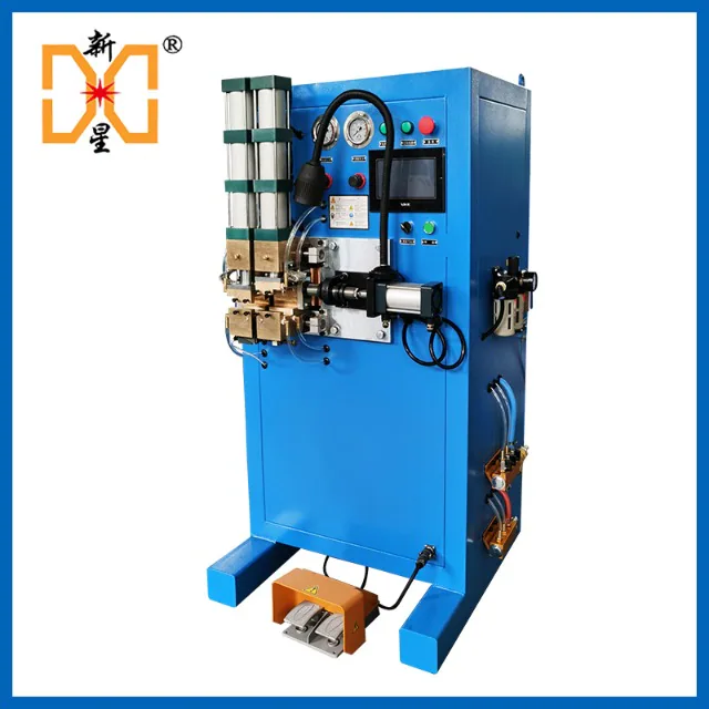
Model: UNG-5 Power: 5KVA CNC UNG multi-strand wire butt welding machine belongs to the single-phase AC resistance butt welding machine category. This welding machine can butt weld 0.75-10 square meters of copper multi-stranded wires, 4-16 square meters of aluminum multi-strand wires and various metal wires, such as steel wires, copper wires, aluminum wires, titanium alloy wires, etc. It is suitable for the welding of round rods and small wires in wire drawing, cable and metal wire processing industries. 1. Xinxing’s 30-year history 2. Always adhere to all-copper welding machines 3. 10-year long design life 4. 20+ years of service life 5. Serving 11,000+ customers 6. CE certified products 7. 90% are repeat customers
-
50KVA pneumatic multi-stranded wire butt welding machine
Model: UNG-50 Power: 50KVA Butt connection: 16-120 square copper stranded wire, 25-120 square aluminum stranded wire, tinned stranded wire φ4-12 copper rod φ4-16 aluminum rod Pneumatic multi-strand wire butt welding machine is one of the resistance welding machines (butt welding machines). A pneumatic butt welding machine developed by Xinxing Welding Equipment Factory in 2005. It adopts pneumatic clamping and pneumatic transverse upsetting, and is equipped with an internal and external full water cooling system and a special butt welding controller, which can accurately adjust parameters. At the same time, it can be used with casings to weld multi-core wire harnesses and single-core copper wires without burrs.
News·Information
Contact Xinxing
- After-sales phone number:400-001-0502
- Pre-sales phone number:133-9510-0070
- Email:cnhjsb@163.com
- Address:Next to Huaming Bridge, 161 kilometers away from National Highway 312, Luoshe Town, Huishan District, Wuxi City, Jiangsu Province

Wuxi Xinxing Welding Equipment FactoryAll rights reserved
 Su Public Network Security No. 32020602001105Su ICP No. 11039752
Service hotline 400-001-050213395100070 new manager
Email:cnhjsb@163.com
Factory address: Huishan District, Wuxi City, Jiangsu ProvinceHuamingqiao Industrial Zone, 161 kilometers away from National Highway 312, Luoshe Town, Huishan District, Wuxi City, Jiangsu Province
Follow the public account
Official WeChat

QR code


How to replace electrodes on small medium frequency spot welding machine?
Summary of information:
The small medium frequency spot welding machine is also called a split-type precision small medium frequency spot welding machine. Although it is small, it can weld quite a lot of products, such as iron, stainless steel, copper, silver, platinum, titanium, and tungsten workpieces, and there are many shapes. When we want to change the material or shape, we have to change the electrodes to adapt to the requirements.
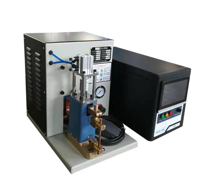
The small medium frequency spot welding machine is also called a split-type precision small medium frequency spot welding machine. Although it is small, it can weld quite a lot of products, such as iron, stainless steel, copper, silver, platinum, titanium, and tungsten workpieces, and there are many shapes. When we want to change the material or shape, we have to change the electrode to adapt to the workpiece we are welding.
This involves the steps of how to replace the electrode. The operation is as follows:
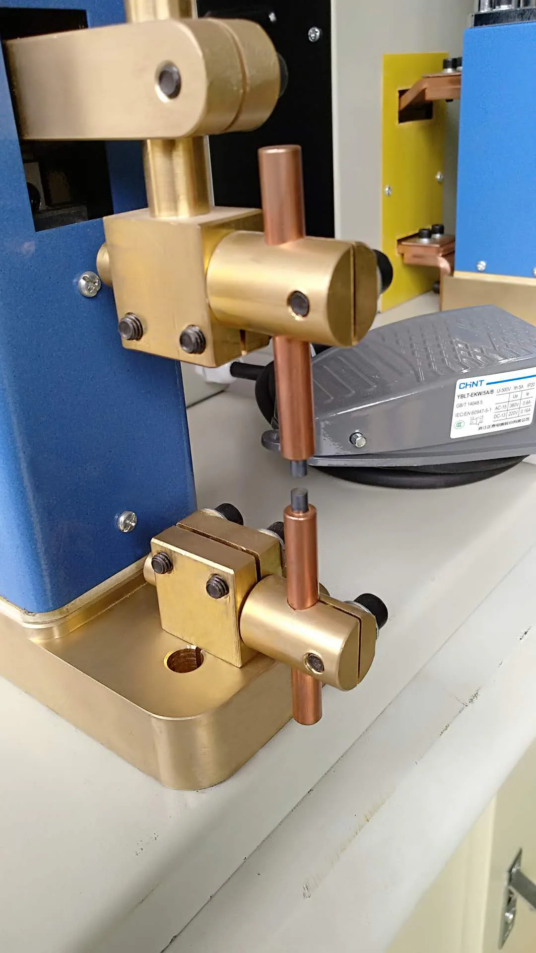
1. Direction adjustment: First use a wrench to loosen the locking screw, then adjust its angle and height to the appropriate position, and finally tighten the screw;
2. Adjustment of electrode head height: First loosen the electrode head height adjustment screw, then adjust or replace the length of the electrode head below the exposed electrode (the electrode head is easily deformed if it is too long), and then tighten the screw.
3. Adjustment of electrode head solder spot width: Then adjust the size of the electrode solder spot according to the size of the workpiece to be welded. Sandpaper can be used to polish.
4. Adjustment of the height of the storage table: First use the wrench to loosen the screws of the storage table, then adjust the workpiece to be welded to a suitable distance from the electrode, and then tighten the screw.
Hot product recommendations