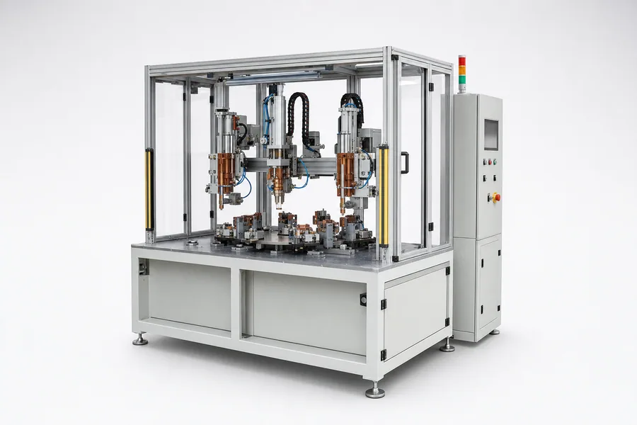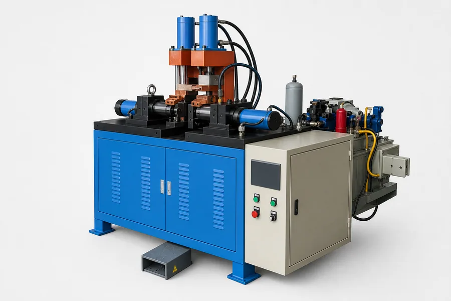
Key takeaways
- Butt welding begins with the ends in contact; flash butt welding heats through controlled flashing before upset.
- Uniform clamping and axial alignment are essential for both processes.
- Cross-section and end condition influence heating consistency.
- Flash containment and post-weld finishing should be included in the project scope.
The core process difference
In resistance butt welding, the prepared ends are clamped together and heated by current flowing through the contact. Once the joint reaches the required condition, axial force completes the upset.
In flash butt welding, the ends approach under controlled conditions and a series of electrical contacts creates flashing across the interface. The heated ends are then rapidly upset. The process can accommodate some end variation, but it creates expelled material that must be safely contained.
How to compare the two methods
The process should be confirmed through trials on the intended cross-section and material. The table is a selection guide, not a substitute for validation.
| Decision factor | Resistance butt welding | Flash butt welding |
|---|---|---|
| Initial end condition | Ends begin in contact and should be prepared consistently | Controlled flashing heats the interface before upset |
| Typical review focus | Contact area, alignment, current and upset | Flash sequence, burn-off, containment and upset |
| Finishing | Upset may require finishing depending on the part | External flash commonly requires a removal plan |
| Machine requirements | Rigid clamps and controlled axial force | Rigid clamps, controlled motion, force and flash guarding |
Workpiece data that determines feasibility
Cross-section matters more than a single outside diameter. Hollow tubes, profiles, stranded conductors and dissimilar sections distribute current and force differently.
- Material grade and any dissimilar-metal combination
- Solid, hollow, stranded or shaped cross-section
- Minimum and maximum section dimensions
- End-cut method and permissible mismatch
- Finished-joint strength, straightness and appearance
- Flash-removal and downstream processing requirements
Define the complete machine scope
The welding power source is only one part of the system. Clamping jaws must carry current, grip without damaging the workpiece and maintain alignment during upset. The project may also require loading support, flash guarding, fume extraction, trimming or inspection.
Final machine selection should be validated with the actual workpiece, material and production target.